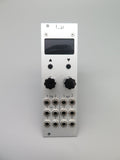
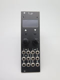
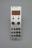
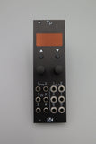
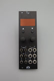
6 x clock generator
- hardware basics, in brief:
- teensy 3.1/3.2 @ 120MHz, w/ 128x64 OLED
- trigger-to-output latency < 100us.
- 2 clock inputs (> 100k input impedance; threshold ~ 2.5V)
- 4 CV inputs (100k input impedance, -/+ 5V, assignable to (almost) any parameter)
- 6 clock outputs (5 digital, 1 DAC (12 bit): 10V (GPIO), -/+ 6V (DAC))
- two encoders w/ switches; 2 tactile buttons.
- 14HP, ~ 25 mm Depth
-
7 modes, selectable per channel:
- trigger sequencer/sequence editor
- clock division/multiplication
- LFSR
- random w/ threshold
- euclidian
- logic (AND, OR, XOR, NAND, NOR, XNOR)
- burst
- DAC (channel #4 only): random, binary, "Turing", logistic, sequencer/arpeggiator
Please Note:
This device uses PSIpower and has NO POLAIRTY on the power header, it can be installed EITHER WAY

Derivative Panel, PCB & Schematic provided by Jakplugg under creative commons CC-BY-SA-4.0 license.
Original CAD file, PCB & Schematic and original design elements provided by mxmxmx under creative commons CC-BY-SA-4.0 license.


