*NEW* 2.1 Firmware! (Feb 2024)
- High Resolution mode for MIDI! 14bit Pitchbend on channels 1-16
Installation Notes: The new firmware must installed using the double-press of the reset button on the back of the module. The "reboot to bootloader" option on the editor is ONLY available for devices running 2.1 or later firmware. With the High Resolution mode enabled, BOTH TRS and USB MIDI send pitchbend on channels 1-16 and whatever CC mappings are assigned on the editor are disabled.
Download the 2.1 firmware New Feb 2024
Online parameter editor:https://misw.us/editor
To connect to the web editor, open the web page in a WebMIDI compatible browser, THEN connect the USB cable to the device. It will take several seconds to connect.
Please Note:
This device uses PSIpower and has NO POLAIRTY on the power header, it can be installed EITHER WAY
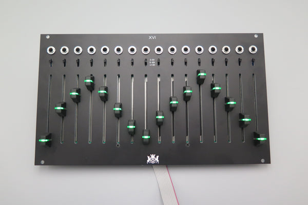
XVI is a 16 channel, 44hp control surface for Eurorack
Features:
- Long throw LED 60mm faders
- 0-5V, 0-10V, -5 to +5V CV ranges per channel
- Micro USB connection, class compliant MIDI Device
- Fully analog CV outputs
- I2C communications as leader or follower
- USB MIDI and TRS B MIDI can be used simultaneously with different mappings in 7bit mode
- I2C, MIDI, and CV can be used simultaneously
- Different color LEDs available separately
Dont forget to order an I2C/MIDI cable if you need one!
I2C: Default State: Follower, Default Address: 0x31
44HP Width, 20mm Depth
Current Draw: +12V 90 mA, -12V 80 mA
Please note: Device MUST be powered by the eurorack power, it is Not USB Powered.
Basic Usage instructions:
Front:
Voltage Select switches: Independent for each channel. Does NOT affect MIDI/I2C data
Rear:
Power Header: Standard 10pin power cable, there is NO polarity for this connection. It can be connected either way. the USB5V header is not used in the euro configuration of the device

MIDI Out Header: This is a 4 pin header but only 3 or 2 connections need to be used. To connect to a DIN cable, either GND, 5 (to pin 5, current sink/aka -), and 4 (to pin 4, current source/aka +) should be used. For internal module to module connections, only pin 4 and 5 should be used. The ground pin is only for the shield in a midi cable, it is never connected on a midi input and isnt necessary for the short module to module lengths

I2C Header: 3 pin header to connect to other I2C devices in your rack, this is an unbuffered connection so cable lengths should be as short as possible (20cm/6" recommended). There are 4.7k pull up resistors on this connection

Connector for Expander: This connects the XVI to the I/O expander. The cable is attached to the expander. Note the keyway below the 1 in on the part, the connecter will ONLY connect one way

FIRMWARE UPDATES:
Firmware update procedure: Connect the Mini USB to your computer, power up the module and press the blue reset button on the back of the module twice (quickly). A new drive will appear on your computer, simply copy the firmware file to that drive (it will give you a warning about copying a file without properties). The drive will disappear once the file is copied and the module will reboot with the new firmware.
UPGRADE INSTRUCTIONS FOR 1.xx Devices:
press the reset twice with USB connected, copy the firmware file to the folder that pops up, it will confirm and the window will close automatically.
The firmware is now unified for F8R and XVI, to identify the device as XVI, DIP switch #4 must be switched to ON
THE DIP SWITCH IS NOW DEPRCIATED, ALL FUNCTIONS IT SERVED ARE NOW DONE VIA WEB EDITOR. The ONLY function is serves now is to identify the unit as 16 channel instead of 8: if only 8 channels are showing up in the editor that means you did not switch DIP channel #4 to on. Mid 2021+ Devices not NOT have this switch

Open Source Licenses:
UF2 Bootloader designed by Adafruit Industries and released under the MIT License
Portions of the code used for this device come from the 16n Faderbank by Brian Crabtree, Tom Armitage, and Brendon Cassidy released under the MIT License